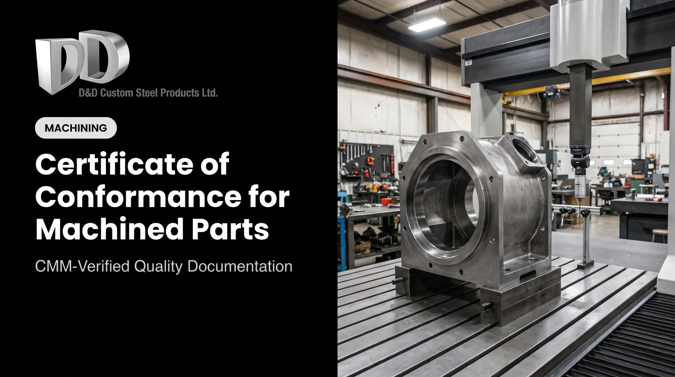

A quality control plan prevents that. It turns drawings, tolerances, inspection methods, responsibilities and acceptance criteria into a controlled production process. This article covers how to build one for castings, forgings, weldments and fabrications, and how to keep it working.
Key Takeaways
- Tie every critical drawing requirement to a method, owner, timing and documented acceptance decision.
- Inspect from incoming material through setup, first-off, in-process checks, final CMM and release.
- Traceability, calibrated equipment and a clear non-conformance procedure are essential for OEM work.
- Tailor the plan to the part, customer and risk. Don't copy a generic template.
What Is a Quality Control Plan for Large Part Machining?
A quality control plan is a documented set of requirements, inspection activities, acceptance criteria, responsibilities and corrective-action procedures. It verifies that a machined component conforms to its drawing and customer requirements. ASQ describes control plans as written descriptions of the systems controlling part and process quality.
Why large parts need a tailored plan
Large components behave differently from small ones:
- Heavy workholding is difficult, and long cycles span multiple setups
- Some features are hard to reach once the part is repositioned
- Stock varies, especially on castings and weldments
- Residual stress can move a part during or after cutting
For example, manual positioning errors caused flange-hole and bore misalignment in a Renishaw valve-body case.
QC versus QA
QC verifies the product and process outputs. QA is the wider system of procedures meant to prevent defects. The plan sits mostly on the QC side but depends on QA systems for document control, calibration and corrective action.
These plans support OEMs in industrial machinery, pumps and fluid handling, mining equipment and power generation, plus fabricators who need finish machining on welded structures.
Essential Elements of a Quality Control Plan for Large Part Machining
Scope, quality objectives and governing requirements
Define the component or part family, material, revision level, production type and operations covered. Then list what governs acceptance: the customer drawing, GD&T requirements, specifications, purchase order terms, material requirements, special processes and any industry or regulatory rules.
State quality objectives in measurable terms, but take every limit from approved customer documents or applicable standards. A plan should never invent a tolerance.
Roles, responsibilities and resources
Assign a named owner for each decision:
- Drawing review and process planning
- Programming and setup approval
- Inspection and non-conformance decisions
- Final release and customer communication
Identify the machines, fixtures, measuring instruments, CMM capacity, qualified personnel and any external testing. Include calibration and verification requirements so measurements come from suitable, controlled instruments. For Canadian calibration evidence, NRC traceability requirements describe an unbroken comparison chain to a stated reference.
Inspection and test plan
Build a stage-by-stage matrix. Each row covers the operation, feature, method, timing, frequency, acceptance criteria, responsible person and record.
| Stage | Example check | Record |
|---|---|---|
| Receipt | Material certificate, heat/lot, visual condition | Receiving report |
| Setup | Revision, datums, workholding | Setup sign-off |
| First-off | Critical bores, faces, hole pattern | CMM report |
| In-process | Features that become inaccessible | Operator/inspector log |
| Final | Full drawing verification | Release record |
Add hold points before irreversible work: after material receipt, first setup, first-off, major repositioning and final inspection. Decide between sampling and 100% inspection from customer requirements, feature criticality, volume, process capability and risk. A one-off heavy casting rarely suits a generic sampling percentage.

Non-conforming product and corrective action
Define how suspect parts are identified, segregated, documented and reviewed. Dispositions, where permitted, are rework, repair, use-as-is, return or scrap. Name who can approve a deviation and how customer approval is recorded.
Recurring issues such as setup error, tool wear, wrong revision, material movement or measurement inconsistency need root-cause investigation. Reworking a part corrects the part; it doesn't prove recurrence is prevented.
Records, traceability and final release
Keep material certificates, heat or lot identification, setup approvals, inspection reports, calibration status, CMM results, non-conformance reports and final sign-off. Part ID, drawing revision, inspector, dates and equipment ID should let you trace from raw material to shipment. Document control must keep obsolete drawings, programs and inspection forms out of production.
Inspection Checkpoints Across the Machining Process
Incoming material and pre-machining verification
Check material identity, certificates, heat or lot traceability and the condition of castings, forgings, weldments and fabrications. An EN 10204 3.1 certificate is a manufacturer declaration validated by an authorised representative independent of manufacturing, not necessarily third-party certification.
Assess weld distortion, casting variation, corrosion, damage and machining allowance before accepting the part. If material doesn't match the purchase order, drawing or approved documentation, stop, segregate it and notify the customer before cutting.
Drawing review, datums and setup approval
Before production, translate the drawing into operations, datums, workholding, inspection points and risk controls. Preserve design intent when establishing datums and realigning across setups.
Confirm:
- Drawing revision
- Critical features and geometric tolerances
- Surface requirements and threads
- Bores, sealing faces and mating interfaces
First-off and in-process inspection
Verify the first piece after setup, programming, tooling and workholding are confirmed, and approve it before continuing. Then check:
- Critical dimensions
- Bore locations and hole patterns
- Wall thickness, face alignment and finish
Prioritise features that will be inaccessible later.
Base inspection timing on tool wear, long cycles, interrupted cuts, multiple setups and operations that add heat or distortion.

Equipment, environment and measurement control
Machine condition, fixture rigidity, tool condition, probing and part stabilisation all affect results. Temperature matters too: ISO 1 sets 20 °C as the reference, and NIST explains that measuring at other temperatures is acceptable when temperature effects enter uncertainty.
Select CMMs, height gauges, portable instruments, gauges or templates by feature size, tolerance and access. Only promise a method that the part and the shop's documented capability can support.
Final inspection, documentation and release
Verify against the current drawing and purchase order:
- Critical dimensions and geometric relationships
- Surfaces, threads, bores and interfaces
- Cleanliness, marking and preservation
Confirm records are complete, non-conformances are closed or approved, and customer documents are ready.
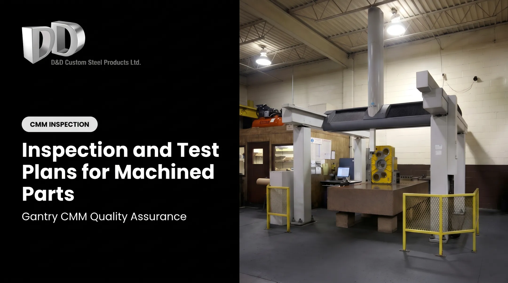
D&D Custom Steel Products, an ISO 9001:2015-certified shop in Stoney Creek, Ontario, offers one example. It machines medium-to-large castings, forgings and fabrications and inspects in-house on a DEA Alpha Image gantry CMM with travel of 78.7 inches (X), 128.9 inches (Y) and 59 inches (Z), supporting in-process and final inspection with dimensional reports.
How to Create and Maintain the Plan
Review requirements and assess process risks
Start with the latest approved drawings, models, specifications, purchase order, material requirements and customer quality clauses.
Walk the full machining route and mark where defects, distortion, wrong setups, tool wear, measurement error or traceability loss could occur. Prioritise critical-to-function features, especially those costly to detect later.
FMEA is a useful preventive technique for this assessment.
Convert the route into control points
Map each operation from receipt to release. For every control point, define:
- What is checked: feature, dimension or attribute
- How it is measured: method and equipment
- When it is checked: frequency or process trigger
- Who records the result: role accountable
- What happens on failure: containment and escalation

Include customer or third-party hold points, but keep the plan usable on the shop floor.
Define documentation, training and communication
Standardise core records, with room for project-specific additions:
- Inspection forms and checklists
- CMM reports and material records
- Non-conformance reports and release documents
Train operators, programmers, setup staff and inspectors on the drawing revision, critical features, methods and escalation. Set a clear path for drawing changes, deviations, supplier issues and customer questions.
Review performance and update the plan
Review findings, rework, non-conformances, customer feedback and lessons learned at defined intervals.
Update the plan when the drawing, material, machine, fixture, tooling, program, inspection method, supplier or customer requirement changes. Keep revision control so the current plan is at the point of use and prior versions stay identifiable.
Common Challenges, Best Practices and Supplier Considerations
Large-part QC plans fail in predictable ways. Watch for these frequent failure modes:
- Relying on final inspection alone
- Using an outdated drawing
- Not inspecting inaccessible features before they're closed off
- Overlooking material traceability
- Calling rework complete without re-verification
Build specific, actionable controls instead: clear acceptance criteria, visible checkpoints, defined sign-offs and escalation rules. "Inspect as required" is not a control.
Supplier checklist for OEM buyers
When you evaluate a prospective machinist, ask:
- How do you review drawings and control revisions?
- How do you manage large-part setups?
- How do you verify critical features?
- How do you control measuring equipment?
- How do you handle non-conformances?
- What traceable inspection documentation do you supply?
For nuclear work, requirements such as CSA N299 apply only when specified, so confirm what your contract requires.
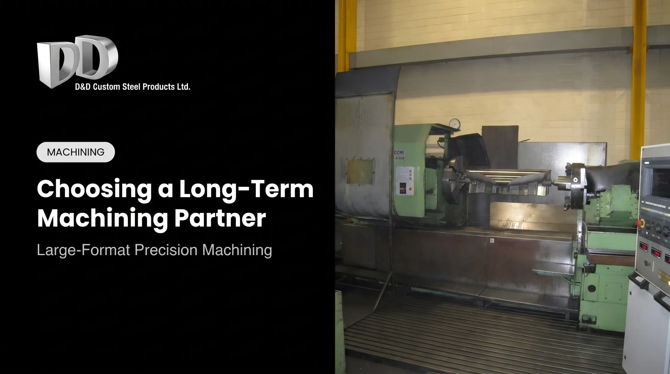
D&D Custom Steel Products supports buyers who need custom, production or prototype machining of heavy components. With over 50 years of experience and ISO 9001:2015 certification, the shop runs heavy-duty horizontal boring mills and lathes (including a Tacchi HD/3 105H with a 20 ton maximum load), plus Mastercam programming and in-house CMM inspection.
Frequently Asked Questions
What is a control plan in a quality department?
A control plan is a documented method for controlling process and product quality. It lists inspections, responsibilities, acceptance criteria, records and corrective actions.
What is the difference between a quality control plan and a quality assurance plan?
A quality control plan focuses on checking outputs and controlling non-conforming results. A quality assurance plan covers the broader systems and preventive processes that deliver consistent quality.
Can you provide an example of a quality plan?
For a large casting: verify material certificates on receipt, approve setup, check key dimensions in process, run a final CMM inspection, handle any non-conformance formally, then release with complete documentation.
What is a project quality plan?
It defines how quality will be managed across a specific project. It can include one or more detailed machining control plans for individual components or production stages.